

Eduard’s Limited
edition kits of the Phantom II were mostly all snapped up after release & although they are still available in some model shops we have not seen many of the
F-4N “Bicentennial Phantom” kits made and we don't know why. Five lovely decal choices, Brassin
Parts and Fabric seatbelts all add to the nice Academy base kit. Let’s see how
our man Brett Reynolds built his in the first part of the build article…

Build review Pt I: Bicentennial
Phantoms
McDonnell Douglas F-4N Phantom II
1/48th scale
Eduard Model Company
Limited Edition Kit No.1190
Available directly from Eduard or their Distributors worldwide.
Build Review by Brett Reynolds
McDonnell Douglas F-4N Phantom II
1/48th scale
Eduard Model Company
Limited Edition Kit No.1190
Available directly from Eduard or their Distributors worldwide.
Build Review by Brett Reynolds
The Eduard limited edition “Bicentennial Phantoms” consists
of the excellent Academy 1/48 F-4B/N Phantom II injection moulded kit, enhanced
with Photo-etch and Brassin Resin Parts from Eduard, and decals designed by
Furball Aero-Design and printed by Cartograf.

Academy originally released their 1/48 F-4B/N kit back in
late 2012. This first release consisted of sprues in white, grey and black
plastic and one clear sprue. This limited edition from Eduard features all the
sprues in grey plastic; along with the one clear sprue.
There are many in-box and build reviews already available
online of the original Academy kit, so I don’t plan go through with an analysis
of each of the sprues. But it is safe to say, Academy’s 1/48 F-4B/N Phantom II
with its one-piece upper fuselage, engraved panel lines and fine detail is
definitely a clear winner in this scale for this version of the Phantom II.
An example of the quality and detail of the base kit can be
seen in the following images.


The Eduard goodies include a pair of resin engine exhausts,
resin MB Mk.H-7 ejection seats for late model Phantoms, a photo-etch cockpit
details, a set of resin wheels and a set of canopy/wheel paint masks.
From Eduard’s Brassin range, each J79-GE-8 engine exhaust
consists of three resin parts on casting blocks and two pieces of photo-etch.

The Martin Baker Mk.H-7 ejection seat consists of two main
parts; the seat itself with the lumbar pad and survival pack / seat cushion
moulded on; and the parachute pack / head rest. Most other aftermarket resin
sets have these casted in one. A couple
of smaller details are also included in resin.

The belts for the ejection seat are a ‘fabric’ type made by
HGW. Photo-etch parts are used for all the buckles.

And to be expected, the Eduard limited edition kit comes
with two sheets of photo-etch parts. One of the sheets consists mostly of
pre-painted cockpit parts.


Brassin resin main and nose wheels accurately match my
references for the F-4B/N’s ‘thin’ tires. They are a straight replacement for
the kit parts.

Finally, an Eduard mask set for the canopy and tire painting
is included.

The kit instructions are provided in a 20-page A4 size
coloured booklet.

The kit provides the option of five patriotic paint schemes
worn by US Navy F-4N’s during 1976 to mark the 200th anniversary of the
American Revolution. Two extensive decal sheets, one of squadron markings, one
of aircraft stencilling, have been designed by Furbull Aero-Design and printed
by Cartograf.
VF-51 Screaming Eagles and VF-111 Sundowners were sister
squadrons in Carrier Air Wing (CVW) 15 aboard USS Coral Sea (CV 43) until late
spring 1976 when the two squadron’s transferred to Carrier Air Wing 19 aboard
USS Franklin D. Roosevelt (CV 42). The decals for VF-51 are from the Coral Sea
deployment with CVW-15. VF-111’s decals are from its time aboard Roosevelt in
late 1976 after the squadron, along with VF-51, was reassigned to CVW-19 for
the carrier’s final deployment.
VF-151 Vigilantes and VF-161 Chargers were sister squadrons
in Carrier Air Wing (CVW) 5 aboard USS Midway (CV-41) stationed in Japan (NAS
Atsugi). VF-302 Stallions were a reserve fighter squadron based at NAS Miramar.
F-4N 151433, VF-161
“Chargers”, USS Midway, 1976

F-4N 150452, VF-151
“Vigilantes”, USS Midway, 1976

F-4N 152293, VF-111
“Sundowners”, USS Franklin D. Roosevelt, 1976 

F-4N 150442, VF-302
“Stallions’, NAS Miramar, 1976

F-4N 150476, VF-51
“Screaming Eagles”, USS Coral Sea, 1976

And the instructions showing colour maps


Cartograf printed and Furball Aero designed, the decal sheets with stencils are extensive!


With so many beautiful schemes to choose from, I finally
settled on the F-4N from VF-151 Vigilantes. The colourful red, white & blue
tail with gold trim was very attractive. I managed to find a few images of the
real aircraft on the internet.


(Source: Unknown
masm.fr-galleryusanavybicent.htm)
(Source: Satoshi
Hashimoto - flickr account ‘vapor_trails’)

(Source: Terry
Killham www.cv41.org)
Construction
As you would expect with an aircraft kit, construction
begins with the cockpit and we’re straight in to using the Eduard photo-etch
extras with a replacement cockpit.
For applying the cockpit side panels, you are instructed to
file off the surface detail from the kit parts and overlay the printed
photo-etch. I thought it would be easier
just to apply a layer of plastic strip the same thickness as the kit part.

Working on the F-4’s Radar Intercept Officer’s (RIO)
position, the instructions have the builder used kit part K8 and provide a set
of photo-etch rudder pedals. These parts are for the dual-flight control
versions of the Phantom II. The US Navy F-4B/N/J/S had no dual flight controls.
A comparison of the USN F-4B and USAF F-4C cockpits can be seen in this extract
from the Squadron-Signal in Action series.
"Squadron-Signal" F-4B Cockpit

"Squadron-Signal" F-4C Cockpit

Looking through my reference material, I recreated the floor
area of the RIO’s position using some plastic strip and the photo-etch parts
PE76 & PE77 as the foot rests.

The right side of the RIO’s cockpit actually contains the
aircraft’s refuelling probe, with this vertical wall covered by a fabric cover.
Eduard provides a photo-etch version of the vertical wall cover but I thought
it would look a little two dimensional, so I stayed with the kit part here.


Jumping into the front seat, I slightly widen the base of
the Pilot’s flight control stick with plastic strip and added the fabric cover
from Milliput between the base and the stick.

Test fitting the kit’s front instrument panel with the
modified control stick.

The RIO’s left side is occupied by the radar control
assembly (larger aft panel) and a utility panel (fwd panel) containing
communications controls and various indicators. I added some additional details
on the back bulkhead of both the Pilot’s and RIO’s position from plastic strip
and lead wire to make things look busier. The cockpit was dry fitted into the
upper fuselage part to ensure no obstructions.

Getting ready for painting, I masked the printed photo-etch
parts of the RIO’s position and the areas on the side panels of the Pilot’s
position. The reason for the latter is
so to glue the printed photo-etch parts directly to plastic rather than over
paint.


A base coat of Model Master Dark Gull Grey was airbrushed to
the cockpit and the rest of the Eduard printed photo-etch panels was glued
down. Hand brush detail painting would follow then a clear coat of Future was
applied prior to some weathering.

Eduard provides a complete replacement ‘multi-layer
assembly’ for the Pilot’s main instrument panel. The printed detail on the
photo-etch is very eye catching and matches the real aircraft. I added some
plastic strip to the back of the side panels to provide some more support when
gluing to the cockpit tub.


The RIO’s main instrument panel was less straight forward.
First step was to cut off the top of the instrument panel as shown here. I used
a photo-etch razor saw for this job.

Then very carefully you have to remove the right section of
the instrument panel that contains the RIO’s radar antenna control stick. This
leaves a small amount of plastic to which the replacement photo-etch would
attach. I tried to temporarily support it with some Dymo tape but it eventually
broke off, so the builder needs to be a little cautious with handling this
part.

Next was to remove the remaining raised detail and apply the
printed photo-etch for the RIO’s instrument panel. Sorry, I forgot to take a
photo of this step. So skipping forward, like with the cockpit tub, I masked up
the printed photo-etch and airbrushed the base grey colour to the exposed
plastic part.

The instrument panels were airbrushed with a clear coat
(Future) prior to a little detail painting and an oil wash.

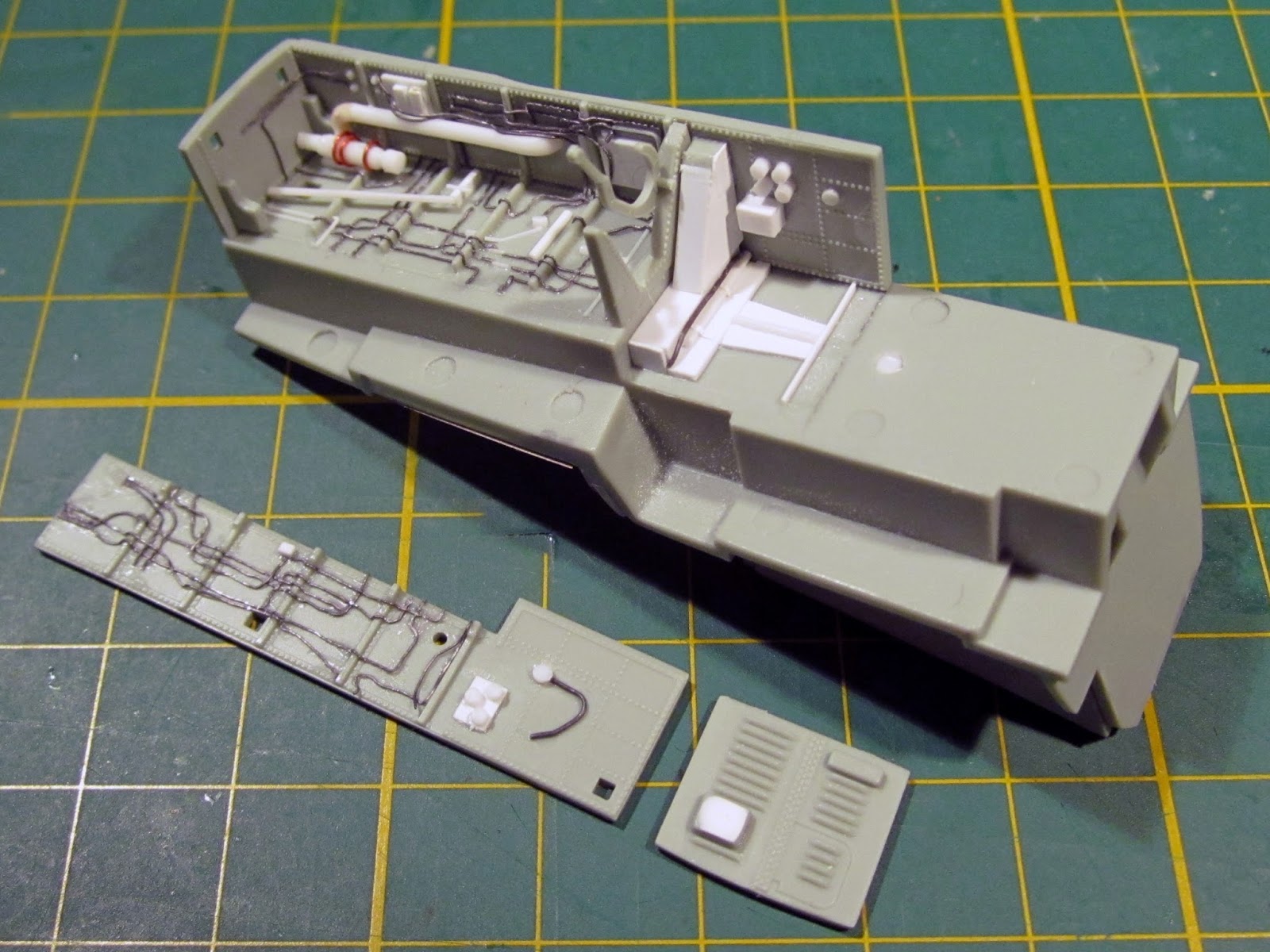
In-between the cockpit assembly, I added additional detail
to the inside of the upper fuselage part in way of the Pilot’s position.
Airframe structure and switch boxes created from plastic strip. A piece of lead
sheet was used to create the fabric linings and the wiring was a mix of copper
and lead wire.

Eduard provides photo-etch details for the fuselage/canopy
sill including the mechanical rod locking mechanism for the canopy.

It should be noted that the locking mechanism for the canopy
on the right side of the RIO’s cockpit is not visible as it is covered by the
fabric blanket lining, so do not use photo-etch part PE54.

Back to the cockpit tub painting, I applied a burnt umber
oil wash for weathering effect and a little dry brushing to bring out the
surface detail. Finally a flat clear
coat of Model Master Lacquer seals it all.


The main instrument panels receive a similar oil wash to the
cockpit tub. A little latex masking agent was applied over the dials to protect
from the flat clear coat and maintain the glass look.

And again the same weathering was applied to the cockpit
sides of the upper fuselage part.

One thing missing from the kit is a Pilot’s engine throttle.
I quickly made a throttle from two vertical strips of Evergreen plastic and
three cuts of round rod. Painted black, the finished throttle does the job.

Final assembly of the cockpit sees the fitting of the
Pilot’s and RIO’s main instrument panels to the tub.


The underside of the cockpit tub and four side walls forms
the nose wheel bay. Additional detail was added with Evergreen plastic and
various sizes of lead wire.

I taped a thick size strip of plastic on the assembled nose
wheel bay to prevent the wheel bay door actuator arm getting broken off. It
mostly worked until it got accidentally broken off.

The multi part design of the main wheel bay kit parts allow
for some excellent detail on the side walls, something not possible if it was
moulded into the wing part.


But as usual, ejection pin marks turn up in the most
inconvenient spots. Discs of plastic card filled the recessed pin marks and the
raised marks were removed as much as possible.

The main wheel bays are assembled with the landing gear
struts in place. To assist with alignment, I used the Tamiya thin liquid cement
to weld the parts together then inserted them into the lower wing section for
adjustment.


When happy with the alignment, I secured each wheel bay to
the lower wing section. Before gluing the upper and lower wing sections
together, the speed brake recesses need to be fixed. A small gap appears
between the forward edge of the speed brake and the lower wing section. I
blanked this off with Evergreen strip styrene.

With the upper and lower wings assembled, I added additional
detail and wiring to the each of the main wheel bays.


More ejection pin marks appear in the speed brake and main
landing gear doors.

I found during this build there are a few omissions in the
Eduard instructions compared to the Academy instructions. One such example is the location holes for
the antenna on the underside of the air intakes (Parts K16 and K18 on Page 8).
Another is the location holes for the antenna on the spine of the upper
fuselage (Part Q39 (x2) on Page 11).

Each air intake consists of two parts. The length of the
intake is too short and the end to narrow, but this is designed to create an
illusion of greater depth as if the engine face is further away than what it
actually is.

The fit alignment between the two halves is quite good but
does require some sanding.


I also used some ‘dissolved putty’ from Mr. Hobby, which is
basically styrene goo, along the seam line.


The trailing edge of the top and bottom of the variable
intake ramp has an air vent and is not blanked off like the kit part. I opened
up the part and thinned down the edges on both this part (G21, G22) and the
inside panel (G23, G24).


I then add thin
plastic strips to represent the air vent detail.


A picture of the real thing can be seen in this extract from
the Squadron-Signal Walk Around series.

With the intakes finished, I sprayed the internal surfaces
with Tamiya White Primer (decanted from the rattle can and sprayed via
airbrush). ALCLAD2 dark aluminium was used on the engine front face.

Before closing up the intakes, I scratch-built an airflow
indicator in each intake. I also masked up a demarcation line for the intake as
it was easier to do now than when all assembled. Note the tape doesn’t go all
the way to the edge. This gap and about a 1mm of the tape will be covered by
the variable intake ramp but the tape will remain easily removable.

One of the highlights of this kit is the addition of a set
of resin J79 engine exhausts from Eduard’s Brassin range. Each exhaust consists
of three grey resin parts and two photo-etch parts.

I used ALCLAD2 lacquers to bring these parts to life. All
resin parts were primed with Tamiya semi-gloss black. The colour variation of
the Phantom’s J79 engine internal and external surfaces can vary greatly, so
how you decide to paint and weather them is an individual choice. I suggest
picking a reference photo and go from there.

The afterburner tube (RP1) of the exhaust develops a
greenish coating over time. But a running J79 also deposits a lot of ‘soot’
from those famously smoky engines. I airbrushed an lighten shade of Model
Master Zinc Chromate green followed by ALCLAD2 Burnt Iron along the high points
of the corrugated exhaust tube, more prominent at the exhaust face engine. A
black oil wash would be applied to help bring out the fine detail followed by
some soot and rust coloured pastels.

Inserting the flame holder (PE97) can be tricky. Make sure
you file off the photo-etch attachment points from the part otherwise it will
catch the edge of the afterburner tube.


The exhaust faces were painted in ALCLAD2 Jet Exhaust.

The instructions
provide a good drawing of how the engine parts should align.

The detail of the nozzle’s turkey feathers and actuator rods
is excellent. Here they are with an initial coat of ALCLAD2 Burnt Iron.

Back to the fuselage construction, the kit provides the
upper fuselage section as a single piece similar to Tamiya’s 1/32 kit. This is
great as an upper glue seam is eliminated but mould lines from the multi-part
injection mould are evident. The upper fuselage section will need to be cleaned
up first.


As the fuselage starts coming together, here you see the
intakes and engine exhausts fixed into position. I also applied two-part epoxy
around where the resin engines attach to the fuselage for extra bond strength.
Last thing you need is the engine part falling into a closed up fuselage. Note I’ve also left off the exhaust nozzles.
During testing fitting, I found I could fit the nozzles after the fuselage was
fully assembled. This would make painting easier in this area.

Before closing up the fuselage, I decided to quickly add a
set of Auxiliary Air Intakes by Aires (4578). These are virtually a drop in fit
and are painted prior to fitting. But I found the doors provided by Aires are
too long, so I’ll use the kit parts here.

The Aux Air Intakes are fixed with super glue then some
extra support provided by some plastic strip and two-part epoxy.

View of the painted
Aux Air Intakes installed.

Another quick
improvement is the addition of brass Pitot tubes by Master (48049).

All the
sub-assemblies are starting to come together.

One at a time the intake assemblies are fixed to the
fuselage. To make sure everything aligns at the same point, I used a wooden
craft stick to act as a splint with the clamps.

The forward fuselage requires a little cleaning up along the
gluing seam. This is not a panel line and needs to be removed. Tamiya white primer was sprayed to test the
results.


After the forward fuselage was cleaned up, the nose cone was
then fitted, but not before adding some nose weight. Lead fishing sinkers held
with two-part epoxy.

The single piece nose
cone fits neatly to the forward fuselage.

I will glue on the
AN/ALQ-126 chin pod after the glue dries.

Moving onto the outer wings, I unfortunately discovered both
had been severely warped. Here is the one of the outer wing parts against a
steel ruler. I broke out one of my other
Academy F-4B kits to check if this was an inherit problem. Fortunately they
were fine so this set of warped wing tips might have been unlucky occurrence.

“So how could I fix this?” I thought. I submerged the outer
wing part in very warm-to-hot water, slowly increasing temperature until I got
some softening in the plastic. Then the part would be weighed down in an
attempt to flatten it. The process was repeated a number of times but I
eventually got the part to flatten down to something that was acceptable.
However, fixing one problem usually leads to another. The hot water disfigured
the wing tip (R) as seen in this photo compared to an undamaged part (L).

Solution was to rebuild the wingtip by removing the damaged
section and replacing it with a length of round plastic rod.


The navigation light bump was added to the leading edge and
everything was shaped and faired in. White primer was used to check the
finished repair.

The fuselage and wing
assembly was one step closer.

The F-4N used the slotted stabiliser. As discovered by most
reviews out there, Academy made the mistake of making the fixing points of the
slotted stabiliser perpendicular to the leading edge rather than the correct
way which is parallel to the centreline of the aircraft.

The solution to fix this seemed daunting at first but was
fairly simple. First I marked the position of each of the fixing points, then
using a photo-etch saw, cut a slot into the leading edge which was at the
correct parallel angle.


After removing the incorrect kit detail, I glued a length of
0.25mm plastic strip into each slot using Tamiya extra thin cement. Don’t worry
about the amount of excess plastic strip, it will get trimmed down.


Next everything gets
sanded down and faired in. I was happy with the final result.


After finishing off the main construction, I was back to the
cockpit. The backside of the RIO main instrument panel was a little sparse, so
I added some detail from styrene rod and strip to represent the instruments.

Lead wire was added
for the mess of cabling and connectors.

Everything was painted in Model Master Aircraft Interior
Black and dry-brushed with a medium grey.

The front instrument cowling and HUD was painted in Model
Master Aircraft Interior Black. HUD glass was yet to be added here.

The reinforced glass centre section of the front windscreen
was represented with a light coat of Tamiya acrylic clear blue.

More Eduard photo-etch details and mirrors are provided for
the Phantom’s two canopies. Here I also
applied the Eduard supplied mask set, but had to do my own masking for the
inside surface.


On the underside of the nose next to the left air inlet
scoop for the Environmental Control System is the Total Air Temperature probe
(kit part O11). There is no mark on the kit’s exterior or interior where this
part should be correctly positioned.
After looking at my reference photos, I marked and drilled a hole so I
could pin the part.

Another positioning of a part which wasn’t clearly defined
is this ECM hump under the starboard (right) wing. I initially glued it the
wrong way around and as usual, afterwards found a pic which clearly showed the
correct orientation as shown here. As you can tell from this pic, I found the
error after I started painting.

The wing pylons are generally very nice out of the box.
However, I did rebuild the sway braces with plastic strip, plastic discs using
a punch & die set and brass rod.

The finished LAU-17
missile pylon with the LAU-7 missile rails for the AIM-9 Sidewinder.

The outboard wing pylons with the weapons adapter mount in
lieu of the wing fuel tanks. Again sway braces were rebuilt with plastic strip,
plastic discs using a punch & die set and brass rod.

I originally planned to display the kit’s refuelling probe
in the deployed position. However the kit part was somewhat terrible. Here’s the kit part compared to the fuelling
probe from a Hasegawa A-4 Skyhawk kit and a pic of the real thing. I planned to
cut the probe tip off and replace it with the Hasegawa part.

Here is the modified refuelling probe. In the end I didn’t
use it, mostly because I couldn’t seem to get the thing to sit at the correct
angle. I’ve seen finished builds of the Academy kit with this part looking
fine, so I might have done something wrong. I’ll try again on my next F-4
build.

Part II of this article can be seen here on TMN in a day or two – stay tuned!
Brett Reynolds
Thanks to Eduard for
sending this kit to build - it is available directly
from Eduard or their Distributors worldwide.
