


Brett Reynolds
is a very clean and thorough builder and has graced us here on TMN with many a
nice article and build – today he presents part I of II on the build of the
lovely kit of the Eduard F6F-5 Hellcat
in 48th scale. Today’s article concerns the build and
alterations he made to the kit whilst the second part will be the finishing and
painting of the Hellcat – Ok here we go…

Eduard Weekend Edition 1/48
Grumman F6F-5 Hellcat
Kit
No: 8434
Kit
type: Injection Moulded
Parts: 5x coloured
sprues, 1x clear parts sprue, 1x decal sheet
Build
Review by Brett Reynolds
Available
from Eduard Directly
at this link
Brett's build of the Eduard Weekend Edition 1/48 Grumman F6F-5 Hellcat - Pt II:Paint & finishBackground
The
Grumman F6F Hellcat was a carrier-based fighter aircraft conceived to replace
the earlier F4F Wildcat in United States Navy (USN) service. The Hellcat was an
erstwhile rival of the faster Vought F4U Corsair for use as a carrier based
fighter. However, the Corsair had significant issues with carrier landing that
the Hellcat did not, allowing the Hellcat to steal a march as the Navy's
dominant fighter in the second part of World War II, a position the Hellcat did
not relinquish (From Wikipedia).
The
Hellcat developed the reputation of a well-armed and rugged aircraft, which was
relatively easy to fly and maintain for carrier operations. In two years of combat, Hellcats shot down
5156 enemy aircraft in air-to-air combat, the most aerial victories ever scored
by on type of fighter. Only 270 F6Fs were lost in combat, resulting in a 19-to-1
kill ratio.
The
Kit
The
kit consists of the same plastic as the full ProfiPACK editions minus the
photo-etch, paint masks, resin wheels and multiple decal options. The plastic
is cleanly moulded with no imperfections or flashing, but I did notice a slight
misaligned in some of the parts such as the control surfaces and gun barrels.


The
instructions are printed as an A5 size B&W booklet - you can download them at this link.
The
Markings
As
with Weekend-Edition kits, only a single set markings is included. The markings
depict a F6F-5 in the standard USN overall Gloss Sea Blue finish, flown by Lt.
Leo Bob McCuddin of VF-20 off the USS Enterprise, October 1944. Lt. McCuddin
scored five victories over Japanese fighters in three combat engagements, all
in the space of six days. Although he flew “White 71” at least once in combat,
the six victory flags below its cockpit probably represent the aircraft’s
tally, rather than any single pilot (Source:
Osprey Aircraft of the Aces No.10).
The Build
As
with most aircraft kits, we start off with the cockpit. After a little clean
up, fit of the kit parts was straight forward, consisting of a cockpit floor,
rear wall, side consoles, seat and front instrument panel. Here the parts are dry-fitted with the
fuselage.


Since
I had already started gluing the kit cockpit before deciding to use the
photo-etch set, I had to pinch the cockpit parts from the other kit as well,
hence the change in colour of the plastic.

It
is necessary to remove certain raised details from the side consoles in
preparation for fitting the photo-etch parts.
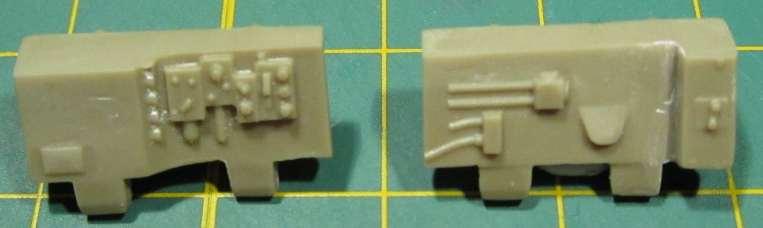
The
kit provides a separate front instrument panel with no surface detail for use
with the photo-etch parts.

The
cockpit sub-assemblies were readied for painting. I placed masking tape over
the areas where photo-etch parts would later go. Never the best trying to glue
metal onto painted surfaces.
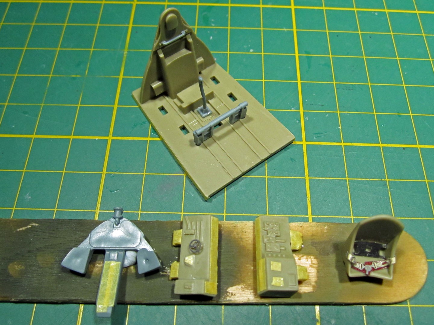
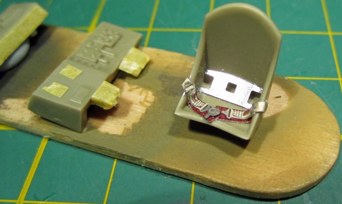
However
I did glue the lap belts in placed before painting. These were nicely
pre-painted, but I usually make a mess of gluing these after painting the seat,
so I decided to glue them into the position I wanted first and then repaint
them.
The
whole cockpit was painted in Model Master Interior Green FS34151 which was a
near perfect match to the Eduard pre-painted photo-etch. The pre-painted
photo-etch parts were attached with CA glue. Details were hand painted before
airbrushing a clear coat of Future. I
then proceeded with a light oil wash of burnt umber and a little dry-brushing
of Model Master Chrome Silver to highlight and represent worn paint coatings.
In hind-sight, I might have applied another coat or two of the oil wash to bring
out the detail a little more.

A
coat of Model Master Lacquer Flat Clear was airbrushed before final assembly of
the cockpit components. Note: a liquid latex masking agent was applied over the
instrument dials before the flat coat so they maintained a shiny glass look.


In-between
the painting of the cockpit, I started work on the sub-assemblies; cowling, stabilisers,
wings and engine.
The
Hellcat has a distinctive front-end look with the lower chin intakes serving
the aircraft’s oil cooler, supercharger and intercooler. This shape has been
difficult to represent in injection moulding and resin replacements are
available, but I think Eduard has produced the best out-of-the-box attempt of
this part.

The cowling sides have ejection pin markings on the
internal surface which should be cleaned up.

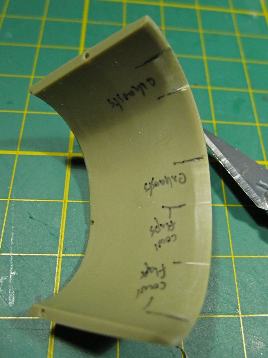
Testing
fitting the cowling with the fuselage, I marked off the areas where the engine
exhausts poke through and where the cowling flaps are. I filed down the plastic
here to sharpen the trailing edge for a more realistic scale thickness.

Some
fine mesh was added to the back of the supercharger intake.

The
cowling halves were glued to the front face one at a time. Note the correct
alignment of the horizontal panel line between the cowling front face and side
parts.

The
horizontal tail surfaces comprise of three parts; upper and lower stabiliser
halves, and the moving elevator surface. A large tab on the elevator slides
into a recess in the stabiliser which locks the elevator at the zero position. However, the elevators on parked Hellcats are
usually seen drooped so I decided to do some modification here.
A
special note; the stabiliser and wings have a stand-off peg at the inboard side
of the internal cavity which is there to hold the shape of the wing/stabiliser
to ensure a correct fit with the wing/stabiliser root in the fuselage halves.
So don’t go cutting this off.

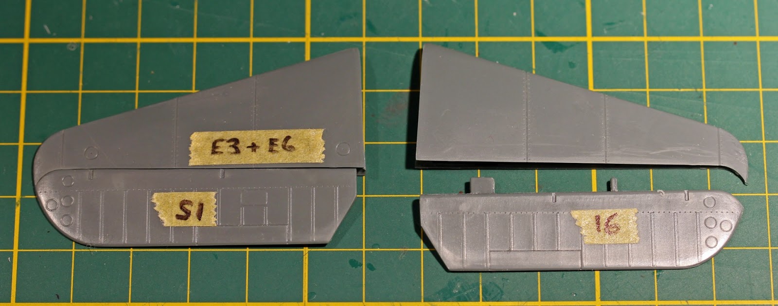
The
image below shows an unmodified elevator (top) and a modified elevator. The
recesses for the hinges have been cut out and the tab connections removed.

A
pair of hinges was made from plastic strip for each stabiliser. I could then
tape the elevator at the desired angle before gluing. I left this towards the
end to avoid accidental breakages.

Dry
fitting of the wings exposed a moulding alignment issue with the gun barrels.
Any attempt to clean these up would result in oval-shaped barrels, so I decided
I would replace them with brass tube at final assembly. The barrels were cut
off and recesses were drilled out of the block.


The
flaps were attached to the upper wing halve first then I added some tabs of
plastic strip on the trailing edge of the internal cavity of the top wing to
provide some extra support when assembling the wing halves. The wheel well and
gun barrel block were also attached at this time.

Like
the elevators, the wing ailerons have a tab which slots into their respectively
recesses. Like the gun barrels, the ailerons had an alignment issue and
required a bit of cleaning up and some plastic card to close up any gaps
between the wing and aileron.


The
wheel wells are nicely detailed out-of-the box and are finished off with a few
detail parts.

The
wingtip lights for the Hellcat are actually a coloured light with a large clear
cover. I drilled a small recess into the corner of the clear part and filled it
with the appropriate coloured paint.

The
light was super-glued into the wingtip and faired in. The clear part was then
sanded and polished to a smooth finish.


The
detail of the kit’s P&W R-2800 engine is reasonable and could be painted up
to look the part, but I decided to replace it with a resin engine from
Quickboost. The resin engine requires a bit of clean-up to remove the casting block
and the thin casting tabs behind each of the cylinder heads. It should be noted
this resin engine is not suitable if you want to do the full open engine display.
Eduard Brassin does a very nice R-2800 for this purpose. The Quickboost is
great for improving that front-end view.


To
fit the Quickboost engine, cut off the kit’s attachment point, leaving about
1mm.


Two
things missing from the Quickboost resin engine for the builder to add are the
push rods and the ignition wiring harness. The pushrods were made from brass
tube with the wiring harness from copper wire.

I’ve
read a few reviews and comments saying the chord of the three-blade Hamilton
Standard propeller being too large. I probably agree with that, but with some
sanding, the blades can be reshaped. Below is a pic of the kit part next to a
painted prop from a Tamiya 1/48 F4U-1D kit which is the same propeller.


To attach the propeller to the
resin engine, I drilled out the engine and inserted a length of 2mm diameter
aluminium tube. The propeller hub received a piece of styrene plastic tube,
drilled out to match the aluminium tube. You can also see in this image the
in-progress painting of the engine. The crankcase was painted in neutral grey;
the cylinder heads flat black and dry brushed with aluminium. The whole thing would
receive a oil wash mix of black and burnt umber.

The
tail wheel required a little clean up. The lightening holes were drilled deeper
for more realism. The tail wheel needs to be attached when joining the fuselage
halves together.

The
main landing gear and locking mechanism is acceptable but I removed the moulded
on wiring and replaced it with copper wire.

The
main wheels are provided as separate tyres and wheel hubs. Assembled, I found
the main wheels to look a little narrow at 4.3mm wide; this is more associated
with the prototype aircraft. I thought the tyres from the Tamiya 1/48 F4U-1D
kit were closer to the correct scale width at approximately 5mm. I added a
spacer to the gluing edge of the tyre. It’s important to remember to add a
spacer to the wheel rim as well to match the added width of the tyre.


There’s
no tread on the kit tyres, so sanding the widen tyre smooth is not a problem. There
are aftermarket options available if the builder wants a tyre with tread.

The
fuselage halves line up very well but the locator pins are very small and give
way easily. Take your time and you’ll have minimal clean up on the seam. Areas
that I found needed the most clean up were forward of the canopy and underside
around the oil cooling air intake. Don’t forget if you want to use the external
fuel tank to cut out the tab in the fuselage aft of the oil cooling air intake.


If
your dry fitting while assembling the wings and stabilisers was successful,
joining them to the fuselage should be easy. The kit is very well designed and
the fuselage wing/stab roots hold their corresponding parts at the correct
dihedral.


Any
small gaps in the wing root were filled with Milliput and smoothed out with
water before it cured.

The
kit external fuel tank, while appearing to be correct in size and shape, it is
missing the prominent centreline seam that runs round the tank. There is also a
version of this tank that has the seam running horizontally. Quickboost make
both these style of tank.

The
tank is secured on the real Hellcat with the help of two metal banding straps,
Quickboost provide these as photo-etch metal parts. Referring to my references
these straps go round the tank and go vertical until attaching to the aircraft.
I first glued the tank to the slot which was cut out of the bottom of the fuselage.
Gluing one end of the first strap in position I quickly learnt the photo-etch
metal straps were too long, nearly reaching the wing.


The
Quickboost instructions weren’t much help when trying to work out if I did
something wrong, so only solution I had was to cut the straps in half, then
trim the length of both so they meet up in the middle of the tank underside.

Another
small improvement was to replace the kit’s solid engine exhausts with 1.2mm
diameter brass hallow tube.


Almost
ready for painting; first was to mask and paint the canopy both sides with the
Interior Green colour used for the cockpit. The front canopy was then glued to
the fuselage.


OK that is it for the construction - on to the painting and finishing to show you just how good a result Brett got from this simple kit in Pt II tomorrow..
Brett Reynolds
Thanks to Eduard for sending us this
hellcat kit to build – you
can get it at this link from the Eduard Website

References
Aero
Detail 17 – Grumman F6F Hellcat (1996)
Dann,
Richard S. – Walk Around No.9 – F6F Hellcat (Squadron-Signal Publications
1996).
Kinzy,
Bert – F6F Hellcat in Detail & Scale (Squadron-Signal Publications 1996).
Tillman,
Barrett – Hellcat Aces of World War 2 (Osprey Publications 1996).