


Build Guide Pt. II:
North American P-51D Mustang
MENG Models
Product No# LS-006
Scale: 1/48th
Product Link
Price: ¥3,840/ USD $34.06/ €32.19 from Hobbylink Japan
Started: November 2016
Finished:.......
In Box Review
Build Guide Pt. I
Build Guide Pt. III
Finishing guide Pt. IV
Today: Build Guide Pt. II the build continues...


In Box Review
Build Guide Pt. I
Build Guide Pt. III
Finishing guide Pt. IV
Today: Build Guide Pt. II the build continues...
Unfortunately, the tailwheel needs to be installed in the fuselage at this time. I say unfortunately because this makes it much more prone to damage during the rest of the build as well as requiring more masking effort. I usually find some way to detach undercarriage parts for later assembly but in this case, I could find an acceptable solution and so here it sits :)

With the main fuselage joined its time to add the cowlings.

Whilst the fit of the cowling parts looked ok when loosely dry fitting them, I found that when it came time to bring them all together for glue they did not really want to co-operate. Because the two plastic parts were giving me so much grief and kept pushing each other out the way I wondered if they would interfere with the clear windscreen part F4 later on down the track. Sure enough - if I attached B30 and B31 in place and then tried to fit the clear windscreen part it would not slide in and would have required trimming. I therefore decided to do all three parts as a package now and ended up needing a clamp to make them all stay put while the glue dried. I really don't know how you would get this lot to work if you tried to assemble without glue ??

The end result looked fairly good. There were still some slight gaps between the parts but I would be able to fix that with Milliput later on. As this point, I offered up the wings to the fuselage for a test fit. As you can see here this presented no issues.

Moving now onto the main undercarriage and wheel well. It was about now that I started to seriously consider whether I wanted to build this model wheels up or wheels down. In the end I decided on somewhere in between !!

As I was doing my research for this build I watched several YouTube videos of restored Mustangs taking off and landing. It occurred to me that capturing that moment just after becoming airborne when the gear was retracting would make for an interesting display. This picture shows best the sort of thing I am aiming for.

Of course, nothing is ever easy in modelling (right?) and as I took a closer look at the retraction sequence and precisely what happens to the main undercarriage struts as the aircraft leaves the ground I realised that some minor modifications to the kit struts would be needed. In this picture the aircraft is still not quite airborne and as you can see the oleo struts are still fully compressed. This is how the kit struts were engineered as if the aircraft was stationary on the ground. Perfectly accurate but not what I needed for my model. I also noted several other items I needed to address for a proper take-off configuration such as the flap position and rear radiator door.

A few seconds later and the aircraft has just left the ground. Notice how the oleo struts are now full extended and because the wheels have fallen away from the wing the main gear doors no longer cover them like they did in the previous photo. I now understood that I would at the very minimum need to modify the main gear struts by extending the oleo to this configuration. It was time for the razor saw ...

With a total of four cuts, I was able to affect the needed modifications. Here you can see on the bottom strut that I have used brass rod (for rigidity) to represent the extended strut. The scissor link rods have also been repositioned to show how they have extended to take the weight of the wheel.

To make sure the length of the new extended strut was accurate (or at least close) I fitted the doors to see where they now sat in relation to the main wheels. The top unit now looks just like the above photo when the aircraft is off the ground whilst the lower (unmodified) unit looks like it should when the aircraft is on the ground.

So far so good, the main gear had the right "sit" for my desired display, but what about having them attached at an angle half way through the retraction sequence. For this I needed to modify the attachment point to the wheel well and replace the Meng plastic with a brass pin which allowed me to pivot the gear to any desired angle, just like the real P-51.

With all the modification work now complete it was time for some paint on the main wheel well. Interior green (same as the cockpit) was used with a very light wash to bring out some of the detailing. I don't get carried away with super detailing wheel wells much anymore.

Next up was assembling the wings with flaps, ailerons and gun muzzles.

The leading edge gun parts B9 and B10 were not a very good fit. There was not way known I could have kept them in place without glue. Even with glue the fit was not great and I was left with gaps that needed to be dealt with (thanks again Milliput).

It's worth noting that the Meng kit flaps are designed to be displayed in only one position, full down (as if the aircraft is at rest on the ground). You don't get alternate parts and as I found simply cutting off the locating lugs and trying to rotate the flap to the closed position did not work. At first I thought it was just this little notch on the inboard edge that was stopping the flap retracting, but even after I quickly cut that flush the flap would not sit properly in the retracted position.

To overcome this flap issue I had to aggressively trim down and reshape the flap leading edge so it would properly fit into the wing at my desired angle. This was unexpected but in the end not that much of a drama.
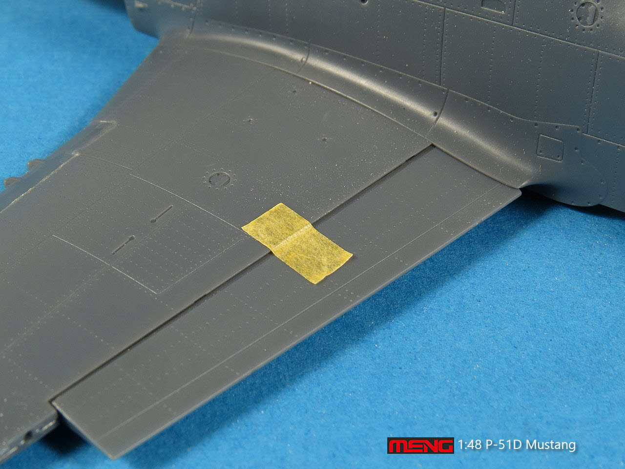
The reworked flap was now glued slightly extended so that it matched the photo of the real aircraft we saw above in the take-off configuration. Note the use again of Milliput (the creamy coloured filler) in the flap to wing join.

The reworked flap as seen from below. As I re-profiled the flap leading edge to get it to fit into the wing cavity much of the rivet detail was lost. This was added back using a needle tip once sanding was complete.

Next step was to marry the wing and fuselage. Repeated test fittings showed that this would present few problems with virtually no gaps visible. The radiator assembly is installed after the wing and helps to lock it into place (assuming you don't use glue). The lower engine cowling (part A17) is also installed after the wing and completes the inboard leading edge assembly. One error in the Meng instructions is that youneed to leave the radiator rear shutter door attached when displaying it opened. You would remove it and instead use part B22 if you wanted the door closed.

One of the more visible features of the Mustangs nose is the carburettor intakes on each side. Meng provides you with the grill parts but with the holes blanked up. Its an easy enough job to drill each one out (if you are so inclined).

A good view of the wing to fuselage join. No filler will be needed here.

With the wing firmly in place, the radiator housing is now ready to be slotted into place.

This is one of the few joints that I would have felt comfortable not using glue, it was very firm. I did need to do a little trimming to get it all lined up.

Likewise, the lower nose section was a very neat fit. One of the join lines needed to be removed with filler as it was not on a natural panel line. For this task, I used Tamiya Basic Putty. Notice the small spots where I used Milliput to close up any gaps on the panel lines. Milliput is great for this type of panel line work as it dries hard enough to be scribed without cracking (unlike normal styrene fillers).

A final view of the radiator housing and slightly deployed landing flap. As you can see I opted to leave the radiator door open.

A little more Tamiya putty was used on the port side wing leading edge and cowling seam to eradicate those pesky gaps.

The main gear and clamshell inner doors are prepared next. An optional part B28 is provided to allow you have the clamshell doors closed. This would happen whenever the engine is running and hydraulic pressure is present (eg taxiing etc). The only time these doors are open is during the gear retraction sequence or when the aircraft is powered down and hydraulic pressure bleeds off. Note once again the error in the Meng instructions where they say to use part B22 to display the radiator flap in the open position. Part B22 would be used if you wanted the door closed.

The main undercarriage components have been mostly completed. I quite like how the clamshell doors are moulded integrally with the wheel bay sidewall. This will make installing them at the end of the build so much easier. The modified struts look good and only require some minor extra painting (chrome on the oleo) before the wheels can be attached.

The clamshell doors are a very neat fit. The main gear doors had some noticeable sink holes which I easily fixed with some Tamiya putty. I haven't test fitted yet with the wheels attached so I hope they don't stick out too far and hit the clamshell doors.


Meng provides a choice of the two common types of drop tanks carried by the P-51. The longer 108-gallon tank was made from compressed paper and was used for one flight only. Interestingly they could not fill up these tanks too soon before flight otherwise they would soak up the fuel and become weakened. The all metal 75-gallon tank had no such limitation and could be bought back if the pilot had no need to jettison them for combat.

I opted for the all-metal tanks and have painted them with Mr Color Silver. Notice the slightly rough surface on the tanks which is not caused by the paint but is present on the plastic surface. I need to triple check the rest of the model for similar roughness as NMF's are very unforgiving to such surface blemishes.

Once you have selected you preferred stores you attach them to the wing using pylon parts B11 and B12.

This is one place where I think the snap fit nature of this kit will come in handy. The pylons are a solid fit to the mounting holes in the wing but I'll still use glue in any case. Notice once again that rough texture of the drop tank. I think these guys might just get stripped and sanded back a bit.

Approaching the end of the assembly, next up is the canopy and windshield. Remember that I opted to install the windshield (part F4) back with the engine cowlings to ensure those parts all fitted correctly. You will have to deal with the seam line running down the middle of the canopy as well. Finally, I did not install the canopy before the rear fuselage top section as suggested here by Meng, that was way too dangerous to the health of the canopy in my opinion.

The mating up of the clear parts was near perfect. I think I would be struggling to slide a piece of paper between the canopy and windshield. The canopy itself was dipped in Future (after sanding to remove the mould seam) and then glued to the fuselage with several drops of CA (super glue).

Before attaching the canopy I drilled a small hole in the top through which the antenna cable passed (from the seat headrest to the tail). For this, I used a product called EZ Line which is used mainly by railroad modellers for things like power cables etc. It is very stretchy (so very forgiving) and I find it ideal for antennae wires for most scales. I plan to gather it up and hide it under the masking tape on the canopy during painting.

Our very last assembly step is to attach the tail and rear fuselage top section. This top section (part C5) is designed to join the main fuselage along the natural panel lines and hence avoid a seam which needs removing by sanding. Tamiya did exactly the same thing in their 1/32 P-51 kits.

After an initial dry fit test early on I decided that I did not want the canopy on the model when I installed this part. It's no problem to make a small cut on the canopy guide strut to allow it to drop fit at the end. I'm glad I made this choice as the fit of the rear fuselage part was not perfect and needed some TLC.

The empennage assembly was trouble free and the horizontal stabilisers self-aligned and locked into place. The rudder was secured with a couple of drops of liquid glue.

With assembly now complete, its time to prepare for painting. Check back soon to find out which scheme I select.

Gary Wickham
Thanks to Meng Models for sending this kit to Gary to review and then build. It is available no thru Meng's Distributors Worldwide.

More of this kit's construction is coming in the next few weeks in two more articles. See as Gary finishes construction and then paints, weathers and applies a base to this kit.