


From Magic Factory
Kit No #5001
1/48th scale
Plastic injection model kit
Photo-etch included
Four Marking choices included.
Cockpit masks included
Price: $96 USD from Hobbylink Japan
Magic Factory Website & Facebook Page
.webp)
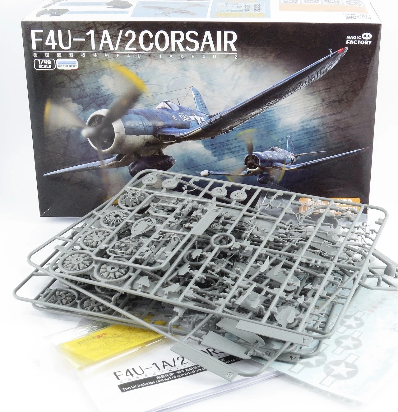
Magic Factory is a new Chinese based kit manufacturer and for their first aircraft release have chosen the Vought F4U-1A/2 Corsair in 1:48th scale.
This release is listed as a limited edition 1+1 dual combo and has parts to build both an F4U-1A and F4U-2 night-fighter variant.

The kit comes with two complete wing sprues allowing the model to be built with wings folded or extended, flaps up or down. A full R-2800 engine is provided and cowling flaps in the open or closed position. Decals are by Cartograph and offer four sets of markings options.
This dual combo boxing includes:
- Plastic parts: two full kits, one F4U-1A and one F4U-2
- Marking options: 4
- Decals: Cartograph
- PE parts: yes, seatbelts
- Painting mask: yes, outside only
One of the most recognisable airplanes in history owing to its unique inverted gull wing design, the F4U Corsair was renowned for its speed, ruggedness, and firepower, excelling as both a fighter and an attack aircraft in support of ground forces.
The F4U-1A was the first improved variant sporting a taller canopy which afforded the pilot a much better field of view compared to the earlier "Birdcage" framed F4U-1 canopy. The F4U-1A also had a lengthened tailwheel strut, allowed the pilot better visibility over the long nose.

The F4U-2 was an experimental conversion of the original F4U-1 "Birdcage" Corsair into a carrier-borne night fighter, armed with five .50 in (12.7 mm) machine guns (the outboard, starboard gun was deleted), and fitted with Airborne Intercept (AI) radar set in a radome placed outboard on the starboard wing. Since Vought was preoccupied with more important projects, only 34 were converted from existing F4U-1s by the Naval Aircraft Factory and another two by front line units.

IN THE BOX - Magic Factory 1:48 F-4U1A/2 Corsair Dual Combo (5001)
The box supplied by Magic Factory is surprisingly deep for a 1:48 kit but when you consider this release includes two full kits it is understandable.

The box is full to the brim, without being over-packed as some manufacturers tend to do thus increasing the risk of damaged parts, especially those delicate clear sprues. As is common practice these days, each sprue is sealed in its own plastic bag.
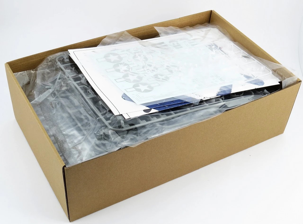
The 24 page assembly instructions are provided in a clearly printed black and white booklet, along with a pair of full-color, A2, double-sided foldouts which provide the details for the four marking and painting options. A single decal sheet is provided and I am glad to see it is printed by Cartograph.

Last but not least are the pre-cut masks for the clear parts and a very small photo-etch fret (seatbelts).

This boxing has some limitations on how you can configure the model(s) during assembly:
- Two identical fuselage sprues are provided.
- Only enough parts are provided to build exactly 1 x F4U-1A and 1 x F4U-2. This means you cannot choose to build two F4U-1As or two F4U-2s, it has to be one of each.
- You get one extended wing sprue (F) and one folded wing sprue (C). This means if you plan to build both kits in the box one will have to be folded and the other extended.
- The extended wings are designed to only allow the flaps to be displayed deployed (down).
- Likewise the folded wings are designed to only allow the flaps to be displayed retracted (up).
- Both open and closed cowling flaps options (for both kits) are included.
- The wing gun bays are provided open on all wing parts. If you plan to display the bays closed you will need to glue the covers in place. Thankfully the fit of the covers is excellent.

HANDS ON - Magic Factory 1:48 F-4U1A/2 Corsair Dual Combo (5001)
As usual we kick off construction with the cockpit. As this is a dual combo kit in which can make exactly one F4U-1A and one F4U-2, Magic Factory have opted to show the different construction steps for each variant as we go along. Be sure to be pay close attention to the callouts and which option you use as in some case (like the cockpit) the parts to be used between variants are quite different.


The front bulkhead and main instrument panel sub-assembly gives us a first taste of the general design and fit of this kit. In short all the parts fit like a glove and the photos you see here are without any glue. For my hands-on build I have chosen the F4U-1A but I expect that the F4U-2 parts would fit just as well.

A quick comparison with the F4U-1A instrument layout shows that Magic Factory have done their homework as everything looks to be in order.

The kit includes two sets of parts for the main IP and each of the cockpits consoles (front and both sides). One set has raised detail (as I have opted for) and the other is completely smooth for those that prefer to use the included decals for the console detail.

To my eye the decals are a bit simplistic and I will be swapping these out for some Airscale/AnyZ instrument decals and hand painting. I think its good that MF offer both options for modellers to cater for varying skills and preferences. I am sure that aftermarket PE and 3D cockpit upgrade sets will appear in time from Quinta, Red Fox and Eduard but for now the old school techniques will have to suffice.

The seat and rear cockpit bulkhead are next, once again small differences, such as headrests and seat framing, between the F4U-1A and F4U-2 are catered for by Magic Factory. One thing to note is that the shoulder straps for the seat belts should not drape over the back of the seat as shown but instead are meant to go over the horizontal bar behind the seat. A simple fix that will make a visible improvement to your cockpit.

When dry fitting the seat frames I was a bit surprised that the horizontal top bar was such a poor match in the center. The easy fix would be to trim the ends then glue the two together but I decided to replace the whole thing with a new section of 20" Evergreen rod as I think this was easier and looks way better.

The photo etch parts are provided on a fret that has no attachment points (notice how each part seems to be floating away from the main fret). They are of course attached to a clear adhesive sheet but the end result means that you simply peel the parts off the sticky backing and they are ready to go (no cleanup needed). This is a nice feature and one I hope other kit manufacturers will adopt.

To help with the bending and curving of photo etch belts I first like to anneal them using the naked flame from a cigarette lighter to heat them (until they glow dull red) and then let them cool slowly (do not dip in water to cool, called tempering, lest they become more brittle). Once cool the belts are far more flexible and you can bend them without kinking. Here you can see the replacement plastic rod (in white) and how I have positioned the shoulder straps over the bar.

As I also had a spare Ultracast resin seat handy I did a quick test fit to see how it looked.

An interesting feature of the Corsair cockpit was that it had no floor. The pilot was suspended above the lower fuselage interior by framing and had raised platforms on which to place his feat, when they weren't on the rudder pedals. The last step of the main cockpit construction is to bring the front, rear and side consoles together to form a new sub-assembly.

The fit of the cockpit parts is very precise and whilst I would have preferred some additional alignment pins for the two bulkheads, the parts sit nicely once you get them in the right spot. The fuselage sidewalls have raised ribbing as per the real aircraft and under a coat of Interior Green (or Bronze Green for the F4U-2) this will all look very convincing.


Assembly of the tailwheel and arresting hook should also be completed at this point. Magic Factory include options to display the hook up and hook down.


Lt. JG Chico Freeman poses on the wing of his Vought F4U-1A Corsair from VF-17 White 34 in New Georgia Solomon Islands Nov 1943.

Once you have squared away the cockpit and tailwheel/hook it's time to join the fuselage halves. Two additional internal bulkheads are needed forward of the cockpit to help the fuselage keep the correct shape.

Once you try and mate up the fuselage halves you can see why those extra bulkheads are needed. The engineering of the fuselage is quite clever as the only place where the left and right halves meet is at the tail. All the rest of the fuselage top and bottom seams have been eliminated and the joins have all been designed to be placed on the natural aircraft panel lines instead.

If this design looks familiar its probably because you have built the Tamiya 1/32 Corsair kit. The design and engineering used here by Magic Factory is virtually identical to the 2014 Tamiya kit. Whether this similarity is by coincidence or intentional it's a welcome feature and assuming the fit of the parts is good, this will save modellers a lot of sanding.

Just like the top, the bottom of the rear fuselage is designed so that the glue seams are along the natural panel lines. Needless to say the parts fit like a glove.

Step 10 and it's time to close up the top and bottom of the fuselage. As the F4U-2 was based on the birdcage F4U-1 you will need to use different parts for the rear fuselage section directly behind the canopy. This is to allow for the rear quarter windows which were deleted on the F4U-1A and later variants.

I was very impressed when dry fit testing the upper fuselage parts. The fit was pretty close to perfect and only the smallest amount of thin liquid glue will be needed to hold these in place without damaging the natural panel line and rivets.


One trick you can use when it comes time to glue these in place is to apply the glue from the inside of the join. This will be possible because as we have seen the bottom of the fuselage is open and more than enough room to fit a brush with thin liquid glue up inside. In this way there is virtually no risk of damaging the seam thus ensuring a drama free assembly.


This overall photo of the assembled fuselage shows just how well the various parts come together. A real credit to the design of the Magic Factory parts.

Vought F4U 1 Corsair VMF 221 White 125 BuNo 02467 with ace Donald Burch Russell Islands 1943

Magic Factory have provided us with, for the most part, a complete P&W R-2800 engine. Despite there being no option for an open cowling to be able to appreciate this, they have included the rear bank of cylinders and some generic exhaust tubing. The design and assembly sequence is pretty standard for 1/48 radial engines with both banks of cylinders having front and rear halves. This does leave us with an almost unfixable seam along the side of the cylinders but for the most these are not seen when looked at from the front.

The F4U-1 and F4U-2 Corsairs were fitted with the Pratt and Whitney R-2800-8 Double Wasp engine. The -8 produced 2,000 hp (1,500 kW) at 2,700 rpm at 1,000 ft (300 m); 1,800 hp (1,300 kW) at 2,700 rpm at 15,500 ft (4,700 m). It was the first production "B" Series engine using a two-stage, two-speed supercharger and with internal engineering changes resulting in increased power and reliability.

The detailing on the engine parts is very good. Whilst not as detailed as a resin or 3D printed alternative, I feel that Magic Factory have done a very credible job of the cooling fin details and the most visible part of the engine, the speed reduction gearbox just behind the propellers. I'm also impressed that they provide a separate ignition harness (with no leads of course).

All the parts are keyed to ensure the correct alignment in relation to one another and this makes assembly a breeze. As you can see, the cooling fin detail on the rear of the cylinders has been left off by Magic Factory but I am happy to give them a pass on this as it will literally never be seen (unless you leave the cowling off and in that case you are going to want to buy a resin replacement engine anyway).

Also note how the exhaust tubes don't bother to extend to the front cylinders, another shortcut by MF. From the front, the cylinder detailing looks just fine as this is the main thing that matters.

Once fully assembled the engine actually looks very convincing. Yes, the connecting rods are overscale and to my eye the reduction gearbox looks a little bit fat but nothing to stress over. Once painted and weathered with oil stains etc this will look very realistic.

Of course all that power from the engine is not much use without propellers to generate some thrust. The F4U-1/2 Corsairs were fitted with a three-blade Hamilton Standard Hydromatic propeller with solid aluminum blades spanning 13 feet 1 inch.

The Magic Factory spinner is slit in two and as can be seen each blade is keyed to ensure proper pitch when inserted in the hub. When test assembling I found this a bit fiddly but I was trying to do it without glue which never helps.

The spinner and propeller makes up into a nice package and everything aligns nicely without any need for tweaking. To my Mk.1 eyeball the body of the propellers looked a bit thick and to check this I compared them to the Tamiya 1:48th part. To the eye and touch the Tamiya parts are noticeably thinner and I feel more to scale than the Magic Factory props. If this worries you, then I am sure Quickboost or Reskit will pop out resin replacements in due course (or pinch the one from your old Tamiya kit).


Offering up the completed engine to the fuselage was met with a gratifying solid click. Even though I had not properly glued all the elements of the engine together, the assembly sat square and I was more than happy with the end result.


All along I had this little voice in the back of my mind saying "lets swap this out for a resin one, it will look much better". Then I slid the cowling over the engine and that little voice suddenly went very quiet. The fit of the cowling is so snug (on the model and the real aircraft) that precious little of the engine is visible at all. So for me, what Magic Factory has provided will be more than adequate.

Vought F4U-1A Corsair VF-17 White 36, Landing CV 17 USS Bunker Hill 14th Sep 1943

One thing I do really like on my radial engine models is to display the cowling flaps open. So I was once again happy to see that Magic Factory provide both open and closed parts for the cowl flaps.

The cowling itself is provided as a single part, which is quite practical for 1:48 scale. The part is molded very cleanly with only three small sprue attachments to be dealt with.


The optional cowling flaps are simple drop in parts depending on how you want to display your model.

A couple of final photos to better show what each cowling flap option looks like when complete - closed...

...and opened.

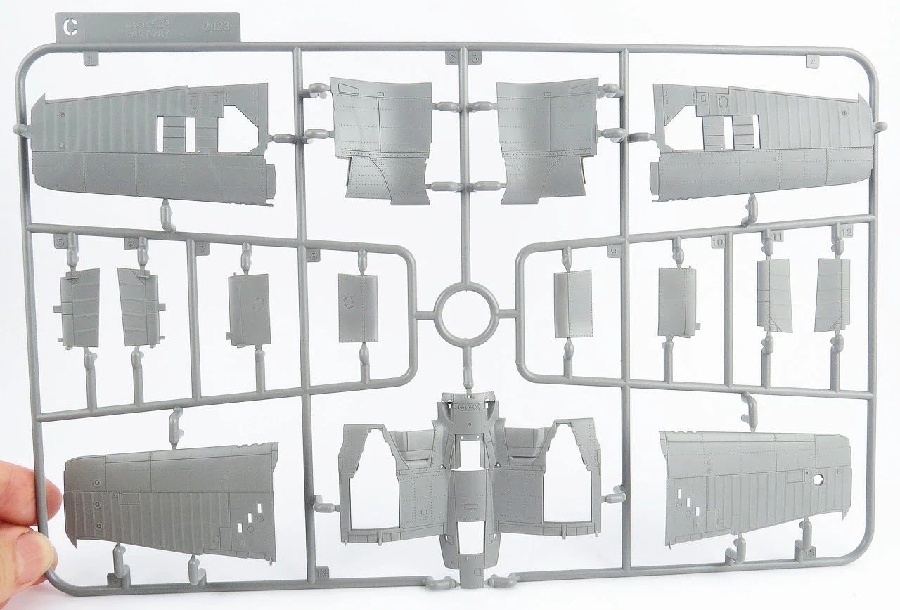
With the fuselage mostly covered off it's time to turn to the wings. This new kit from Magic Factory differs from all previous kits of the F4U in that it includes specific parts to model the wings extended or folded. These are not the same parts which you can choose to display open or closed (as with the Tamiya 1:48 and 1:32 kits) but totally different sprues designed to do one or the other. To start with I will construct the wings extended (unfolded).

Sprue F contains the parts needed to model the wings extended (unfolded). Note that you cannot fold the wings with these parts (unless you decide to cut the wings yourself). The lower wing is supplied as a single part with the upper wings (left and right) in one single piece each. The flaps are also on this sprue and it's worth noting that the ONLY option for the flaps with the wings extended is DOWN. You cannot use the flaps UP parts with the extended wings, so trying to model this kit in flight will not be easy. This to me is a bit of an Achilles heal of this kit but I accept that the designers had to make a difficult choice.

Sprue D also contains parts used in the extended wing option. The main wing spar (D39) is the most obvious but a set of starboard flaps with the square cutout for the step (D36/37) is a strong hint that Magic Factory is intending to release an F4U-1D in the future.

A cursory glance at the plastic shows sharp panel line and rivet detail. As with this entire kit the sprue attachment points are thoughtfully placed so as to make cutting as clean as possible. It's also worth mentioning that at no point did I find an ejection pin mark that was in a place which I needed to clean it up. This is no mean feat so full marks to Magic Factory.


Vought F4U-1A Corsair VMF-215 White 31 at Torokina Bougainville Solomon Islands 10th Dec 1943

Much like the real aircraft, Magic Factory has provided a full main spar that extends the length of the wing across the fuselage. This of course provides great rigidity to the wing part when glued in place. The main wheel wells are built around the main spar.

The main spar and wheel well side walls snap positively into place within the main lower wing. The wing spar extends far enough outboard so as to form the front of the wing gun bays.


To cool the powerful R-2800 engine, both oil and intercooler radiators were needed. Due to lack of space in the fuselage these were placed in the wing root leading edges by the Vought designers.

When offered up the main wing leading edge the radiators slip nicely into place, again the seams are located on natural panel lines. This is literally a gap free exercise. Painting will be a little tricky but with some creative masking I am sure it will be tamed.


I made a bit of a mess with the seam on the bottom of the radiator inserts and will need to fill it and re-scribe. I guess now would be as good a time as any to mention my thoughts on the Magic Factory styrene plastic. I would describe it as a soft-medium hardness and found it very easy to work with. You need to have a light touch with any styrene liquid glue as it will melt the plastic very quickly. This photo also affords us a close up view of the main wheel well interior.

The F4U family was armed with six .50 in (12.7 mm) Browning AN/M2 machine guns fitted in outer wing panels. Magic Factory provide a full set of guns and ammo belts for both kits in the box. The gun bays can be displayed open or closed.


The kit parts, especially the ammo belts, are very nicely designed. I found the mounting points for the guns to be a little bit vague so you will need to pay extra attention to make sure the guns are parallel when you glue them in place.

A full set of gun bay covers is provided and designed to be displayed open or closed.

If you are wondering how good the fit is when closed the answer, as seen here, is near perfect. These panels are sitting in place with no glue.

A Vought F4U Corsair from VMF 218 at Barakoma Airfield on Vella Lavella in the Solomon Islands, January 15, 1944.

The inverted gull wing combined with the wing fold required some interesting engineering by the Vought designers for the trailing edge flaps. The Magic Factory kit allows the extended wing option to only install the flaps in the down/extended position.

This port wing, shown her with its full complement of control surfaces installed. The aileron and outboard flap are fabric covered whilst the inboard two piece flap are metal. The fit of the extended flaps is very clean and the parts did not fight me at all to get them in the right place.

A view of the extended flaps from the underside. As you can see everything self aligns with the hinges matching up perfectly, even with no glue at this point. It was about now in my dry build that I was starting to really like this kit.

Once you are happy with the wing it's time to mate it with the fuselage.

Magic Factory earn full marks for the way this join is designed. The fuselage overlaps the wing roots and this results in a gap free, near perfect join with no effort at all.


As mentioned earlier, one of the unique features of this new tooled F4U is the provision of specific parts to model the wings extended or folded. These are not the same parts which you can choose to display open or closed (as with the Tamiya 1:48 and 1:32 kits) but totally different sprues designed to do one or the other. It's now time to construct the wings folded.

Sprue C contains the parts needed to model the wings folded. Note that you cannot unfold the wings with these parts. The flaps are also on this sprue and it's worth noting that the ONLY option for the flaps with the wings folded is UP. You cannot use the flaps DOWN parts (from sprue F or D) with the folded wings. As I mentioned above this is a bit limiting but consistent with what even Tamiya did with their 1:48 kit.


A F4U Corsair undergoing final checks at the Vought assembly line, circa 1943.

The heart of the folded wing is sprue E, which contains the fold internal details and the all important wing spar with the folded angle built in. This is where the fold will gain all its strength and will make or break the overall look.

Assembly of the wheel wells is mostly identical to the extended wing with the main difference being the addition of the wing fold detail on the exposed outer edges. The upper wing skin is added and the main part of the wing is ready to attach to the fuselage. This is very neat and especially welcome given it involves no cutting or surgery.

The main wing is seen here ready to receive the outer wings. The outer spars may look simple enough but they are in fact keyed to align with a channel found on the inside of the outer wing panels. Magic Factory has made this whole exercise super simple. Also note that here I have attached the retracted flaps with small sections of tape. These were a click fit. The small square step, visible on the starboard inner flap, will need to be filled and removed as these extra steps were not introduced until the F4U-1D.

The folded outer wings of the Corsair have a distinctive "toed-in" angle to them when folded. Magic Factory have done a good job of capturing that look once the outer wing parts are slid onto the internal spar.

The shape and detailing of the Corsair wing folds have been captured nicely by the Magic Factory team.


I have not yet added all the provided internal bracing and piping parts but the interior still looks accurate and busy.


A final look at the folded wings from the top (note the aforementioned "toe-in") and the bottom.


As mentioned previously, the folded wing option is designed to only allow the flaps to be displayed in the UP (retracted) position. This will annoy some modellers but the complex hinges and cover plates used in the Corsair flap system makes designing a kit that offers complete flexibility very challenging.

A couple of Corsairs in the wild, seen with flaps up and wings folded.

I thought it may be useful to show a quick side by side comparison of the flap down and flap up differences, if for no other reason than to help explain why Magic Factory did not try and provide generic flaps that modellers could decide for themselves to display up or down.

Many other aircraft have simple hinged flaps which can be used for up or down but not so with the Corsair due mainly to its gull wing and to a lesser extent the location of the wing fold.

Turning next to the tail (empennage), Magic Factory have provided us with separate rudder and elevators. Consistent with most of its contemporaries, both friend and foe, the Corsair employed fabric covered control surfaces. Over the years I have seen many manufacturers attempt to design an accurate representation of the doped stressed fabric finish.

Thankfully Magic Factory have steered away from the classic scalloped fabric effect. Even the most cursory comparison of real aircraft shows that the fabric is never so loose that it sags in this way. Indeed the only real giveaway that an aircraft has fabric parts is the slightly raised ribbing used to secure the fabric, much in the same way rivets are used for metal skin. A side by side comparison with one of the Magic Factory elevators and rudder reveals they have captured the concept, if not quite the scale of the ribbing.


Bear in mind that these photos have been taken with a very close up macro lens which tends to exaggerate things. I can confirm that to the naked eye the ribbing on the kit parts looks pretty good and under a coat of paint the ribbing will be even less prominent.


I'll probably knock off some of the sharp edges on the ribbing with a couple of swipes with some flexible abrasive but other than that I won't be loosing any sleep.
Once you take a step back with the camera the fabric covering and ribbing starts to look more realistic and to my eye is acceptable for 1:48th scale.

By the time you reach Step 31, most of the main airframe is complete. What remains is the undercarriage and external stores then onto painting. To accommodate a folding wing, Vought designed the main landing gear to retract rearward. The F4U-1A was fitted with an improved undercarriage oleo struts which eliminated bouncing on landing, making these the first truly "carrier capable" F4Us. During it service life (and later into post war civil service) there were several types of tires fitted to the Corsair.

The most obvious difference was the smooth tread tires used mainly for operating off carrier decks vs the treaded tires used by the land based Marine Corp aircraft, which operated from rough crushed coral strips.

Magic Factory include two sets of wheels in the kit, each sporting different tire treads. The first is a smooth tread and the second the classic diamond tread. The main wheels have been designed to represent the aircraft with "weight" on (so no good for in flight). The outer hub and tire are molded as one part with the back hub separate. The bottom of the tires are compressed and give a reasonable re-creation of the effect of weight on the wheels and at first glance I felt the amount of sagging looked a bit excessive (almost like a flat tire), however once you take them off the sprue and place them flat on the ground they look just about right.


Despite being molded as one part (or perhaps as a result of this) the diamond tread pattern is very badly molded on both tires. Not sure how this got past the Magic Factory QA check because to fix this will require a bit of effort or you can opt for a simple replacement with a superior resin offering from Barracuda Studio or the like.


Vought F4U 1 Corsair, VMF 112 White 9, BuNo 02268, Henderson Field Guadalcanal 1943

The F4U-1A was the first Corsair able to carry a drop tank under the center-section. With drop tanks fitted, the fighter had a maximum ferry range of just over 1,500 mi (2,400 km). To allow the Corsair to carry out bombing missions, early field modifications introduced a makeshift bomb rack on the centerline. This could support a 500lb bomb and proved useful enough that a factory built version, by Brewster, was authorised. Magic Factory provide both the Brewster rack and 500lb bomb as well as the center line fuel tank. Check your references as to which you choose to fit to your model.


As a nice bonus, Magic Factory have included in the box a full set of pre-cut masks for the clear parts and wheel hubs. Due to the different canopy layouts between the F4U-1A and the F4U-2 (based on the F4U-1 Birdcage) two sets of masks were needed.

The masks are designed to allow you to mask the outside only of the parts (unlike the new generation of T-Face, aka Two Face, masks from Eduard that have both interior as well as exterior masks). The masking material appears to be washi paper (similar to Eduard) and is pre-cut. The outline of each section is also conveniently printed on the paper so you can easily locate each piece.


One each of the clear sprues, J for the F4U-1A and I for the F4U-2, are provided in the dual combo box. All the clear parts are blemish free and crystal clear.


A dry test fit of the F4U-1A canopy revealed the same excellent fit I had come to expect from the rest of the kit. The canopy seems to work pretty well in both open and closed position. None of the internal canopy detail (grab handles, mirrors etc) is provided by Magic Factory but in 1:48 I guess that's to be expected.


The classic lines of the F4U Corsair are captured beautifully in this photo from the Smithsonian National Air and Space Museum.

To get a better overall impression of the "look" of the model, here are some final photos. Nothing about the shape and fit of this kit has given me any reason for concern. Magic Factory have done a very commendable job on the design, engineering and execution.


F4U-1 Corsair #252 (possibly that of 1/Lt. William ‘Bill” Boshart) VMF 224, Marine Corps 4th Marines Aircraft Wing, Majuro Airstrip, Marshall Islands. Planes being readied for fighter patrol due to radar picking up Japanese bombers headed for the Palau Island group, Peleliu, September 19th 1944.

To finish up the "hands on" section, I want to take a moment to share my thoughts on the overall surface detail, in particular the rivets, provided by Magic Factory.
To my eye, the rivets are too large in size and the inter-rivet spacing too large to be suitable for a 1:48 model. I realise this sounds like rivet counting (I suppose it literally is) but I find the provided rivets to be visually distracting. I know that most modellers won't care too much about such things but I specifically enjoy reproducing accurate surface detail and in this case it just bugs me.

In addition to the actual size/spacing of the rivets, I was now curious about the placement of the rivet rows in general. To help me clarify, I superimposed a scale drawing of an F4U-1D wing over a photo of the kit wing. This showed, based on the drawing layout (in red), that almost none of the kits rivet lines are in the right place, nor are they aligned correctly to the wing panel lines. All this information combined has led me to the conclusion that Magic Factory really did not take the same level of care with the rivet detail that they have so obviously taken with the rest of the kit engineering. This is a real pity.
The last point I want to make is that I do not expect model manufacturers to try and reproduce each and every rivet on a scale model. What I do think is reasonable is that any effort made to add rivet detail onto the model should be done properly and not half-heartedly, as seems to be the case here.

COLORS & MARKINGS - Magic Factory 1:48 F-4U1A/2 Corsair Dual Combo (5001)
Four marking options are provided by Magic Factory on the kit decal sheet. Two options for the F4U-1A build and two options for the F4U-2 build. I have to admit I was a bit underwhelmed when I learned that Magic Factory had included an F4U-2 as one of the two kits in the box but somewhere along the line in researching this review I have changed my mind. I think it's great that we finally have a modern tooled kit of this somewhat obscure variant and I look forward to building mine up. Here is a little more info on the F4U-2 to get you suitably motivated:
F4U-2, White 10, VF(N)-101, USS Enterprise.
.webp)

Thirty four F4U-1s were converted into night fighters and given the F4U-2 designation. The main change was the installation of an air interception radar set. The radar antenna was placed in a radome (radar dome), placed two thirds of the way along the starboard wing. The outermost machine gun was removed from that wing to help balance the additional weight. A rudimentary 3-inch radar scope was also added to the centre of the main instrument panel. As normal with night fighters, the exhaust stubs were modified to hide as much of the exhaust flame as possible. Three naval squadrons flew the F4U-2 night fighter in the Pacific (VF(N)-75, VF(N)-101 and VMF(N)-532). Only a small number of this version were built, and those aircraft moved between the three units as required. They were first used on Munda, New Georgia, where the Japanese were making nuisance raids at night. They also served on the U.S.S. Essex, U.S.S. Hornet and U.S.S. Intrepid.
F4U-2, "White 212" (BuNo.02624), "Midnite Cocktail" Originally assigned to Lt. Caniff, but flown by Capt. Howard W Bollman, VMF(N)-532, USMC. Shot down a Japanese G4M attacker with the cooperation of ground navigator over Kagmon Field, Saipan, early morning of April 14, 1944
.webp)

F4U-1A, "White 29" (BuNo. 55995) Lt. Ira Cassius "Ike" Kepford, the top ace (total 16 kills) of VF 17 “Jolly Rogers” U.S. Navy, Bougainville, East New Guinea, Feb-Mar 1944
.webp)

F4U-1A, “White 42" (BuNo.50042) Flown by Lt. J.J. O'Connell, VMFA-321 “Hells Angels”, USMC
USS Kwojapin (CVE-98), July 1944
.webp)

One thing that is always sure to bring a smile to any modellers face is the mention of Cartograph kit decals. Magic Factory have made the right move providing such high quality decals in the box. A quick scan revealed no obvious English spelling mistakes, which can sometimes pop up in artwork from Chinese manufacturers. The colors look very accurate as well so all round this sheet is a winner.
.webp)
CONCLUSION - Magic Factory 1:48 F-4U1A/2 Corsair Dual Combo (5001)
Given the iconic subject, it's not at all surprising that this new tooled F4U Corsair in 1:48 has been so highly anticipated by the aircraft modelling community.
Overall I'm very impressed with what Magic Factory have managed to produce for their first 1:48 aircraft kit. The fit of the parts is excellent, the general design and engineering is clever making the modellers life super easy. With inclusions in the box such as die-cut masks and Cartograph decals the value for money is pretty clear.

The one thing that I don't like about this kit is the surface rivet detailing. It's over-scale and not at all accurate (especially on the wings). It almost feels like the rivet work was rushed at the end of the project and no-one double checked it in any way for suitability and accuracy. This, at least for me, is a real detractor to this kit. Yes, I know it can be fixed with some putty and riveting wheel but Magic Factory would have been far better off opting for no rivets than giving us poor rivets.
Recommended.
Gary Wickham
Check out the Magic Factory Website & Facebook Page
.png)

ASSEMBLY INSTRUCTIONS - Magic Factory 1:48 F-4U1A/2 Corsair Dual Combo (5001)
.webp)
.webp)
.webp)
.webp)
.webp)
.webp)
.webp)
.webp)
.webp)
.webp)
.webp)
.webp)
.webp)
.webp)
.webp)
.webp)
.webp)
.webp)
.webp)
.webp)
.webp)
.webp)
.webp)
.webp)
.webp)
.webp)
.webp)
.webp)